
 E2E Cloud
Connect two firewalls with an IPsec VPN
Join two E2E Firewalls with a site-to-site IPsec VPN tunnel. The VPC behind each one then reaches the VPC behind the other on private addresses. You build the tunnel with the FortiGate’s site-to-site template on each firewall in turn. The firewall you set up first is the local firewall, and the other one is the remote firewall.
Before you begin
Section titled “Before you begin”You need:
- Two E2E Firewalls with the status Running, each in its own VPC. See Create a firewall.
- The public IP of each firewall and the address range of each VPC. Each VPC needs its own address range, with no addresses shared between them. See VPC.
Example values
Section titled “Example values”| Placeholder | What goes there |
|---|---|
<local-public-ip> |
The public IP of the firewall you are setting up, such as 203.0.113.10. It is under Public IP on Manage Firewall. |
<remote-public-ip> |
The public IP of the other firewall, such as 203.0.113.20. |
<local-vpc-range> |
The address range of the VPC behind the firewall you are setting up. It is under CIDR on Manage Virtual Private Cloud. |
<remote-vpc-range> |
The address range of the VPC behind the other firewall. |
<pre-shared-key> |
A long random key that you make up, such as one from a password manager. Both firewalls use the same key. Keep it somewhere safe. |
Sign in to the local firewall
Section titled “Sign in to the local firewall”- In a browser, go to
https://<local-public-ip>. - Sign in with the username
adminand the password from the launch email E2E sent when the firewall first ran.
For more on the first sign-in, see Sign in to the FortiGate.
Move the FortiGate’s screen to port 444
Section titled “Move the FortiGate’s screen to port 444”The tunnel uses port 443, the same port as the FortiGate’s screen, so the screen can stop opening once the tunnel is in place. Move the screen to port 444 before you build the tunnel.
-
Open the FortiGate’s command line: on the screen, or over SSH:
ssh admin@<local-public-ip> -
Run these commands to move the screen to port 444:
config system globalset admin-sport 444end -
Open the screen at its new address,
https://<local-public-ip>:444, such ashttps://203.0.113.10:444, and sign in again.
If neither the screen nor SSH opens, ask support to turn on console access, giving the firewall’s name. The account owner can then choose Access Console from the firewall’s Actions menu.
You can also change the port on the screen instead of its command line. See Move the FortiGate’s screen to port 444.
Create the tunnel from the template
Section titled “Create the tunnel from the template”- On the FortiGate’s screen, go to VPN > VPN Tunnels, and click Create new.
- Select IPsec tunnel from template.
- In Tunnel name, enter a name for the tunnel, such as
vpc peering. - Under Select a template, keep Site to Site selected.
- Click Begin. The VPN wizard opens.
Enter the pre-shared key
Section titled “Enter the pre-shared key”Under VPN tunnel:
- Keep Authentication method set to Pre-shared key.
- In Pre-shared key, enter
<pre-shared-key>. Use the same key on both firewalls. - Click Next.
Describe the remote firewall
Section titled “Describe the remote firewall”Under Remote site:
- For Remote site device type, keep the FortiGate selected.
- For Remote site device, keep Accessible and static.
- In IP/FQDN, enter the remote firewall’s public IP,
<remote-public-ip>. - Leave Route this device’s internet traffic through the remote site. turned off.
- In Remote site subnets that can access VPN, enter the remote VPC’s range,
<remote-vpc-range>. - Click Next.
Choose the interfaces
Section titled “Choose the interfaces”Under Local site:
- Set Outgoing interface that binds to tunnel to port1, the FortiGate’s internet side.
- Leave Create and add interface to zone turned on.
- Set Local interface to port2, the FortiGate’s side in your VPC.
- In Local subnets that can access VPN, check that your VPC’s range,
<local-vpc-range>, is listed. - Leave Allow remote site’s internet traffic through this device turned off.
- Click Next.
Review and submit
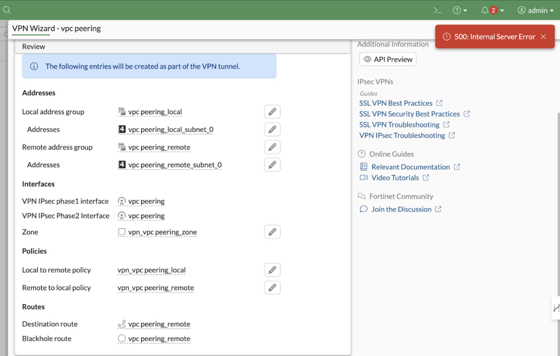
Section titled “Review and submit”The Review page lists what the wizard creates for the tunnel:
- A local and a remote address group, with their addresses.
- The IPsec Phase 1 and Phase 2 interfaces, and a zone, a named group that holds the tunnel’s interface so the policies can use it.
- A local-to-remote policy and a remote-to-local policy.
- A destination route and a blackhole route to the remote network.
- Click Submit.
- If 500: Internal Server Error shows, ignore it and click Submit again.
The wizard creates the tunnel and the items it listed.
Check the policies on the local firewall
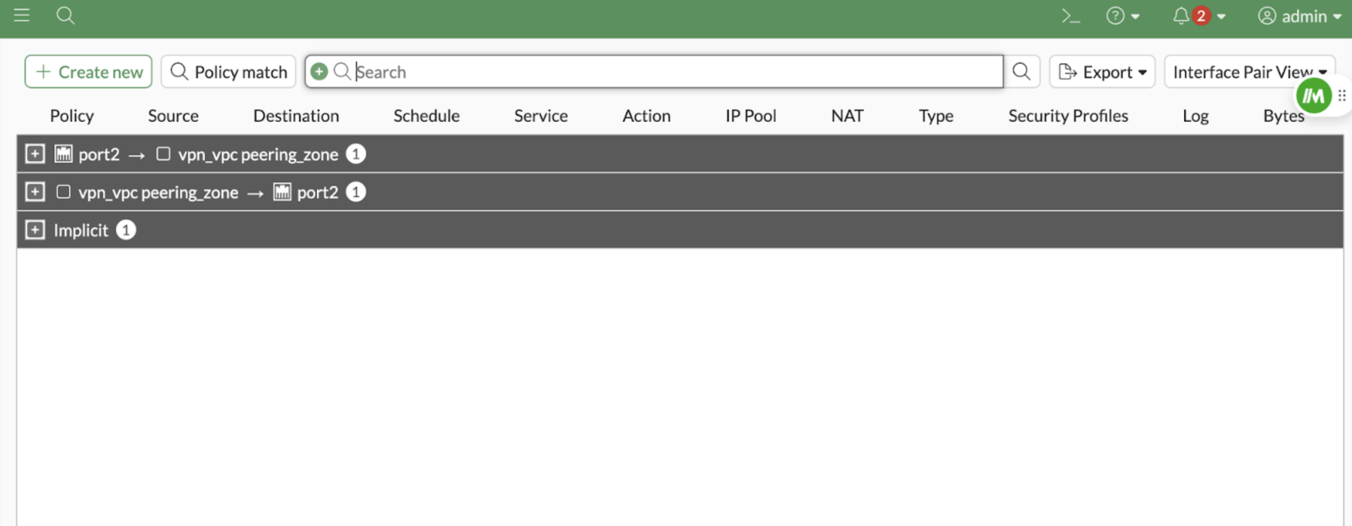
Section titled “Check the policies on the local firewall”Open the list of firewall policies. It shows the two policies the wizard added: one from port2 to the tunnel’s zone, and one from the tunnel’s zone to port2.
Set up the remote firewall
Section titled “Set up the remote firewall”Repeat these steps on the remote firewall, from the sign-in to the policy check, with the two sides swapped:
- Sign in at
https://<remote-public-ip>. - Move its screen to port 444 before you build its tunnel, then sign in again at
https://<remote-public-ip>:444. - In IP/FQDN, enter the first firewall’s public IP,
<local-public-ip>. - In Remote site subnets that can access VPN, enter the first firewall’s VPC range,
<local-vpc-range>. - Use the same
<pre-shared-key>. - Check that its two firewall policies have been added.
Check the tunnel
Section titled “Check the tunnel”- On each firewall, go to VPN > VPN Tunnels. The tunnel shows as up on both.
- On each firewall, open the firewall policies and check that the two policies for the tunnel are there.
The two VPCs are now joined by an IPsec tunnel between their firewalls. For a node to use it, add a route on the node to its firewall’s private IP. See Send a node’s traffic through the firewall. For help with a tunnel that shows as down on either side, see The site-to-site VPN tunnel does not come up.